
Views: 0 Author: Site Editor Publish Time: 2026-08-05 Origin: Site


Directly connecting high-load or noisy field devices to sensitive PLC I/O cards poses a massive operational risk. Voltage spikes from heavy industrial equipment can easily bridge standard terminals. They quickly destroy expensive internal microprocessors. Proper electrical isolation serves as your primary defense against these transient voltage spikes. It prevents dangerous ground loops and stops premature PLC failure. Creating a physical barrier protects your critical control infrastructure perfectly.
Wiring a PLC interface optocoupler relay correctly is essential for maintaining this protective barrier. You must precisely match the specific logic—sinking or sourcing—of the PLC to the relay module. Doing so ensures safe, compliant, and highly reliable signal transmission across your entire control cabinet. You will learn exactly how to identify your logic type, wire the connections safely, and avoid common electrical pitfalls during integration.
Industrial control panels operate in extremely harsh environments. Heavy machinery creates massive electrical noise. Motors start and stop constantly throughout the day. Giant contactors slam shut, generating powerful magnetic fields. You cannot expose fragile programmable logic controllers to this raw, unpredictable environment. You need a robust isolation strategy.
A massive cost disparity exists between various panel components. Replacing a basic interface module costs very little. Contrast this against replacing a multi-thousand-dollar PLC output card. Field devices fail frequently due to water ingress, cable damage, or operator error. A short circuit on the field side can destroy an unprotected PLC instantly. High voltage surges travel up the copper signal wire incredibly fast. Optical isolation provides a necessary sacrificial barrier. It shields your core controllers from catastrophic damage. If a field sensor shorts out, you only lose a cheap protective relay. Maintenance teams swap the damaged module in seconds. The factory resumes production immediately.
Ground loops occur when two connected devices sit at different ground potentials. This voltage difference drives unwanted current through the signal line. It wreaks havoc on analog and digital signals alike. False triggers become common. Optical isolation physically breaks the electrical connection between disparate power supplies. Light bridges the gap instead of copper. This optical gap completely resolves noisy signal issues in the panel. It guarantees signal integrity.
Solid-state optocouplers handle high-frequency switching effortlessly. They rely on light-emitting diodes and phototransistors. They experience zero mechanical wear because they lack moving parts. Traditional electromechanical relays suffer from contact degradation over time. Arcing damages their metal contacts slowly with every cycle. They also switch much slower. Optocouplers provide a highly reliable alternative for fast, repetitive signals like PWM (Pulse Width Modulation).
Relay Type Comparison: Optocoupler vs. Electromechanical
| Feature | Optocoupler (Solid-State) | Electromechanical Relay |
|---|---|---|
| Switching Speed | Microseconds (Very Fast) | Milliseconds (Slow) |
| Mechanical Wear | Zero wear parts | Contacts degrade over time |
| Isolation Method | Optical (LED to Phototransistor) | Physical Air Gap / Magnetic Coil |
| Noise Generation | Silent operation | Audible clicking, potential arcing |
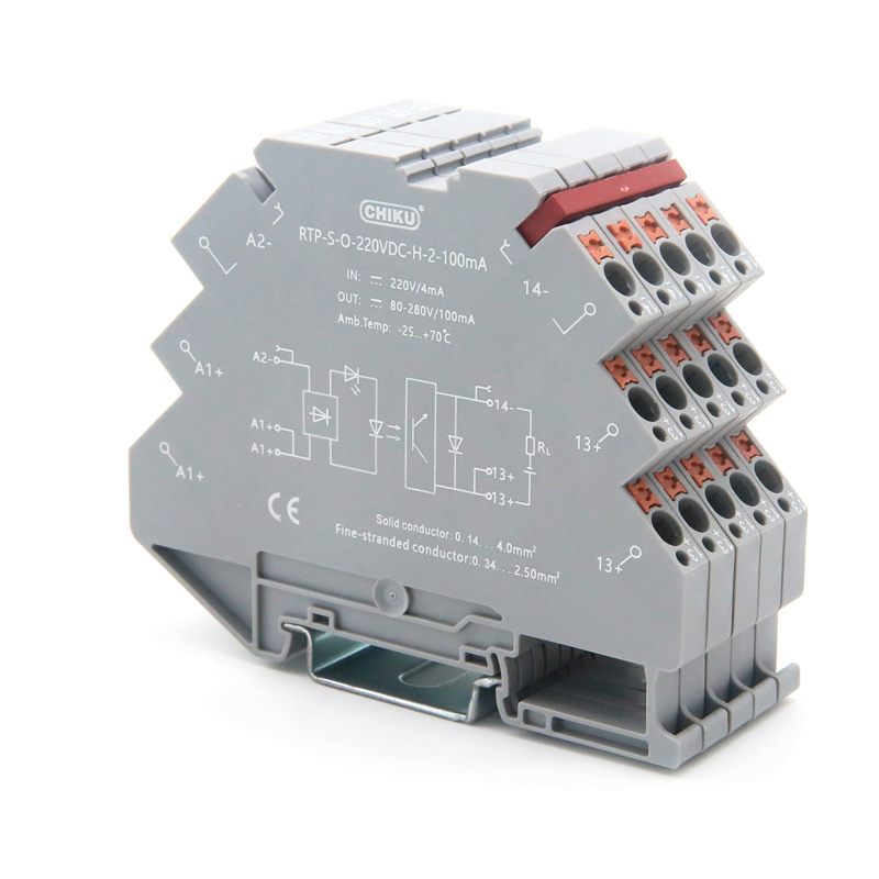
You must align your field devices with your controller's logic. Manufacturers design PLCs to switch either the positive or negative leg of the circuit. Failing to match these logic types prevents proper system operation. Different regions prefer different logic standards. European equipment relies heavily on PNP sourcing logic. Asian automation platforms traditionally default to NPN sinking logic. Mixed-use panels require extreme vigilance.
A sourcing PLC output acts as the voltage source. The PLC supplies positive voltage directly to the relay. This is typically +24V DC in modern industrial panels.
A sinking PLC output operates differently. Here, the PLC provides the ground path (0V) instead of pushing voltage. The PLC acts as a switch to the negative side of the power supply.
You must verify the technical data sheet of the specific optocoupler relay module before starting your wiring. Some modules only accept PNP inputs. Others are bi-directional and accept both. Incorrect polarity can prevent the relay from operating entirely. Reversing the polarity on dedicated NPN modules destroys the internal LED diodes instantly. Always double-check terminal designations.
Common Mistakes During Integration:
Panel building requires strict technical precision. Experience shows rigorous wiring routines prevent troubleshooting headaches later. Follow these steps carefully to ensure robust signal transmission. Loose wires cause intermittent faults. These faults are notoriously difficult to troubleshoot. Proper crimping guarantees a solid physical connection.
Electrical systems behave unpredictably under specific dynamic loads. You must proactively manage transient voltages and stray currents. Demonstrating reliability requires mitigating these unseen threats effectively. Without protection, your solid-state components will degrade quickly.
Switching inductive loads generates significant back-electromotive force (back-EMF). Inductive loads include solenoids, motor starters, relays, and contactor coils. When the optocoupler turns off, the magnetic field around the field coil collapses instantly. This rapid collapse creates a massive reverse voltage spike. This spike can easily exceed hundreds of volts. Unchecked, this high-voltage kickback travels backward along the wiring path.
You must mandate the use of suppression devices across inductive loads. Install flyback diodes in parallel for DC loads. The diode gives the reverse current a safe path to dissipate. AC loads require snubber circuits. RC snubbers consist of a resistor and capacitor wired in series. You wire this network in parallel with the inductive AC load. The capacitor absorbs the high-frequency voltage spike. The resistor safely dissipates the energy as heat. Wire these suppressors properly to your electronic control relay setup. They prevent high-voltage spikes from bridging the isolation barrier. Without suppression, spikes eventually puncture the optical isolation layer.
Solid-state PLC outputs do not behave like mechanical dry contacts. They often "leak" small amounts of current even when turned off. They leak enough micro-amps to cause real-world issues. Highly sensitive optocouplers require very little current to turn on. The optocoupler detects this leakage and stays engaged permanently. Your system thinks the output is on when it should be off.
You solve this by installing a bypass or bleeder resistor in parallel with the relay input. The resistor provides a path of least resistance for the leakage current. It routes the micro-amps safely to ground. This keeps the optocoupler turned off until the PLC sends a true control signal.
Selecting the proper components demands careful evaluation. Scalability and long-term procurement depend on standardizing your selections early. Taking the time to evaluate specific parameters ensures a safer control panel build.
Match the continuous current rating of the relay to the maximum inrush current of your load. You must consider peak startup currents, not just steady-state draw. Optocouplers are generally strictly for low-to-medium current DC switching. Do not overload the solid-state output. If your load requires 10 amps, a standard 2-amp optocoupler will fail immediately. Size your components conservatively.
Cabinet space represents a premium resource in modern manufacturing. Evaluate ultra-slim DIN-rail modules during your design phase. Many manufacturers offer 6.2mm wide profiles. These slim designs save massive cabinet space during large-scale rollouts. High-density panels reduce enclosure sizing requirements significantly. Smaller enclosures save structural framing costs and valuable factory wall space.
Industrial components must meet strict global safety standards. Ensure the selected PLC interface relay carries necessary approvals. Look for UL, CE, or CSA markings on the device housing. Verify it meets stringent isolation voltage requirements. Widely accepted industry frameworks recommend 2.5kV to 4kV minimum isolation. High isolation ratings guarantee safety for maintenance personnel working inside the panel.
Advise your electrical engineers to compile a comprehensive I/O list. Document all field load voltage and current specs precisely. Note whether each device requires NPN or PNP logic. Standardizing your component selection reduces spare parts inventory. Maintenance departments do not want to stock twenty different part numbers. Picking a universal, widely approved device simplifies purchasing. It ensures technicians always have the right replacement part on hand. Do this tedious work before requesting bulk quotes or sample devices from manufacturers. Proper documentation prevents costly ordering mistakes.
Wiring a PLC interface optocoupler relay correctly is a strict exercise in electrical precision. You must match logic types perfectly between the controller and the module. Maintaining strict galvanic separation keeps your automation systems running flawlessly. Proper wiring prevents catastrophic transient spikes from destroying expensive I/O cards. Using suppression devices like flyback diodes ensures component longevity.
Technical buyers and panel builders should review their current schematic standards today. Verify all field load requirements against your module capabilities. Ensure your teams apply flyback diodes to every inductive load. Always consult specific manufacturer datasheets to ensure long-term panel reliability. Taking these actionable steps now prevents catastrophic factory downtime later. Small design checks today yield massive reliability improvements tomorrow.
A: Standard DC optocouplers cannot. To switch AC loads, you must specify a solid-state relay (SSR) utilizing a triac or SCR output, or use an electromechanical relay.
A: This is typically caused by leakage current from a solid-state PLC output card. Adding a pull-down or bleeder resistor across the input terminals resolves this.
A: An optocoupler uses light (LED to phototransistor) to switch the signal with zero moving parts and complete electrical isolation, whereas a standard relay uses an electromagnetic coil and physical metal contacts.


