
Views: 0 Author: Site Editor Publish Time: 2026-08-04 Origin: Site


Specifying relay contact ratings in industrial environments carries incredibly high stakes. A single miscalculation can trigger severe consequences across an entire facility. You might face premature component failure or hazardous contact welding. Sudden equipment downtime becomes a massive operational risk. Many engineers mistakenly view the selection process as simply finding a reliable switch. Instead, the task requires matching precise electromechanical thresholds to specific load behaviors. You must also align these choices strictly to global compliance standards. This article gives system designers and procurement engineers an evidence-based framework. You will learn how to evaluate electrical loads properly. We will guide you through reading datasheet variables accurately. By the end, you will know exactly how to shortlist the correct component for your specific application. The right decision ensures facility safety and continuous, stable operation.
Load type dictates the rating: Resistive, inductive, and capacitive loads require vastly different contact rating calculations due to inrush currents and arcing.
Standards matter: Compliance with frameworks like NEMA ICS5-2017 and IEC establishes the baseline for reliability and safety.
Multiple ratings are standard: A single relay will have varying maximum ratings depending on whether it is switching AC or DC voltage.
Electrical vs. mechanical life: A relay’s contact rating directly impacts its electrical lifespan under load, which is distinct from its mechanical cycle limit.
Engineers often look at a datasheet and focus on a bold headline number. You might see 10A printed clearly on the outer casing. However, relying on a single isolated number remains highly dangerous. Industrial datasheets always list multiple contact ratings. A device might handle 10A at 250VAC. The very same device might only safely handle 10A at 30VDC. We must understand why this dramatic performance difference exists across voltage types.
Consider the core switching dynamics between alternating current and direct current. Alternating current naturally fluctuates in a sine wave. It passes through a zero-voltage point fifty or sixty times per second. This zero-crossing point naturally extinguishes any electrical arc forming between opening contacts. Direct current operates entirely differently. It delivers constant, unyielding voltage. When contacts open under a DC load, the electrical arc sustains itself heavily. The steady voltage continuously pulls plasma across the widening air gap. This phenomenon requires severe derating for DC applications. Manufacturers must limit the maximum DC voltage significantly to prevent continuous, destructive arcing.
We must also distinguish clearly between continuous current and switching current. Continuous thermal current represents what the closed contacts can carry passively. They can carry this specific load indefinitely without overheating. Switching current represents a completely different mechanical challenge. It defines the maximum current the device can safely make or break under active load. Making a circuit often involves handling massive initial energy spikes. Breaking a circuit involves managing the resulting plasma arc. A component might carry 15A continuously without issue. Yet, it might only safely switch 10A actively. Ignoring this crucial distinction leads to rapid overheating and eventual destruction.
The type of load you control dictates everything about your specification process. A general 10A rating does not apply universally across all facility equipment. You must categorize your target load correctly before reviewing any datasheet.
Resistive loads include simple heaters and basic incandescent lighting elements. These components represent the most straightforward engineering calculation. The electrical current remains highly stable upon initial activation. The operating current closely matches the standard steady-state current. Inrush spikes remain minimal or entirely nonexistent. If you control a 10A resistive heater, a basic 10A-rated switch usually suffices perfectly.
Motors, heavy transformers, and solenoids act as inductive loads. These devices introduce severe risks into the electrical circuit. When you energize an inductive load, it resists the sudden change in current. More importantly, when you break the circuit, the stored magnetic energy collapses rapidly. This collapse creates severe inductive kickback. The collapsing magnetic field generates a massive voltage spike across the contacts. This spike can easily reach ten times the nominal system voltage. Severe arcing occurs as a direct result. A relay rated for 10A on a resistive load might fail immediately on a motor circuit. It might only safely handle a 2A or 3A inductive load. You must consult specific motor load ratings on every datasheet.
Capacitive loads include heavy power supplies and commercial LED drivers. These electrical components act like empty buckets when first powered up. They draw massive amounts of current instantly to charge their internal capacitors. This inrush current often reaches 10 to 20 times the nominal operating current. If the nominal load is 2A, the momentary inrush spike might hit 40A. This massive surge causes localized melting on the switch contact surfaces. When the contacts close, they often weld together instantly. You must use specialized hardware designed specifically for high-inrush applications.
Modern industrial panels use tiered switching architectures to ensure safety. You rarely use a massive contactor to switch a tiny micro-sensor signal. Clarifying these operational handoffs optimizes your overall design. A low-current electronic control relay operates perfectly for logic-level signal switching. You use it to interface directly to PLCs or microcontrollers. It handles clean, low-voltage signals beautifully. However, when the circuit demands heavy physical work, you need a different solution entirely. You must step up to a heavy-duty industrial power relay to handle the physical load. This robust component manages the high continuous currents and harsh electrical arcs safely.
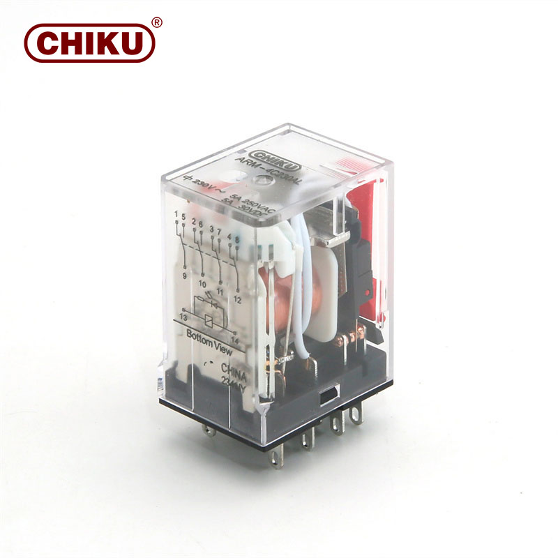
Selecting hardware based solely on basic voltage and current math leaves your facility vulnerable. Global industry standards provide a rigorous testing framework. They ensure components perform safely under worst-case industrial scenarios.
Industry standards like NEMA ICS5-2017 define contact ratings based strictly on operational categories. These frameworks do not just test steady-state performance. They test how the component handles severe fault conditions and high-cycle stress. The standards define specific categories like Pilot Duty or Motor Load. Each category requires unique testing procedures to verify safe arcing limits and thermal boundaries.
You will frequently encounter standardized rating codes on manufacturer datasheets. Codes like A600 or B300 provide a shorthand for maximum thermal continuous current and make/break volt-amperes (VA). Understanding these codes speeds up your component selection process significantly.
NEMA Designation | Max AC Voltage | Thermal Continuous Current | Maximum Make VA | Maximum Break VA |
|---|---|---|---|---|
A600 | 600V | 10A | 7200 VA | 720 VA |
B300 | 300V | 5A | 3600 VA | 360 VA |
C150 | 150V | 2.5A | 1800 VA | 180 VA |
You must position standard compliance as an absolute non-negotiable requirement. Non-compliant hardware introduces severe fire hazards into the control panel. Using properly rated, NEMA-compliant devices ensures facility safety. It also guarantees insurance liability compliance. Ultimately, sticking to standardized components ensures long-term operational stability.
Common Mistake: Do not assume European IEC standards match North American NEMA standards exactly. Always verify the specific regional testing criteria required for your installation site.
Even perfectly specified components degrade over time. The physical acts of making and breaking circuits slowly destroy the internal contact materials. You must predict this degradation accurately to plan maintenance schedules.
Engineers often confuse mechanical life and electrical life. Mechanical life defines the absolute total cycles operated without any electrical load connected. Manufacturers often boast mechanical lifespans reaching ten million cycles. Electrical life defines the cycles operated under the fully rated electrical load. Electrical life is always dramatically shorter. A device boasting ten million mechanical cycles might only survive one hundred thousand electrical cycles at full load. Always design your system around the electrical life metric.
Datasheets provide derating curves to help you predict actual operational lifespans. You must learn how to read these manufacturer charts. The charts plot expected lifecycles against operating temperature, switching frequency, and load type.
Operating Temperature: Higher ambient temperatures reduce the current-carrying capacity. Heat prevents the internal coil from cooling properly.
Switching Frequency: Activating the switch fifty times a minute degrades contacts exponentially faster than activating it once an hour. Rapid switching traps heat inside the enclosure.
Voltage Fluctuations: Operating consistently near the maximum voltage limit accelerates material transfer across the contacts.
The actual metal alloys used on the contacts impact performance heavily. Standard Silver Nickel (AgNi) provides excellent general-purpose switching. It resists basic wear and maintains low electrical resistance. However, if you face high-inrush capacitive loads, you need different chemistry. Silver Tin Oxide (AgSnO2) resists contact welding far better under massive inrush spikes. Selecting the right alloy extends the module's lifespan significantly.
Translating all this theory into a final purchase decision requires a disciplined approach. Follow this systematic framework to evaluate your component options effectively.
Step 1: Define the Absolute Maximums. First, map out the maximum open-circuit voltage present in the system. Next, calculate both the maximum steady-state current and the absolute peak inrush current. Never size your components based purely on steady-state numbers.
Step 2: Identify Environmental Constraints. Factor in the ambient temperature inside the sealed control panel. Evaluate any heavy vibration risks near large motors. Determine enclosure sealing requirements. For extreme environments, you might need RTIII wash-tight sealing to prevent dust and moisture ingress.
Step 3: Evaluate Form Factor & Modularity. Determine physical installation needs. Decide if the application requires a direct PCB-mounted layout or a bulky panel-mount configuration. For applications demanding rapid maintenance, specify a plug-in electromagnetic relay module. This modular design allows technicians to swap out degraded switches instantly without rewiring the entire socket base.
Step 4: Verify Fail-Safe Requirements. Ensure your selection aligns perfectly with system safety architectures. Decide what must happen during a total power loss. A normally open (NO) configuration drops the load safely when power fails. A normally closed (NC) configuration keeps the critical load running. Your choice dictates the fundamental safety logic of the machine.
Best Practice: Always build a 20 percent safety buffer into your final current calculations. This thermal margin accounts for unexpected facility voltage spikes and high summer ambient temperatures.
Specifying the right contact rating requires moving far beyond baseline voltage and current numbers. You must account for dynamic load behavior, aggressive inrush currents, and inevitable electrical life decay. Approaching this task systematically prevents catastrophic equipment failures. Ensure you rigorously evaluate manufacturer datasheets. Pay extremely close attention to thermal derating curves and load-specific performance data. By matching precise electromechanical thresholds to your specific environment, you guarantee long-term reliability.
As a next-step action, we highly recommend consulting your technical sales engineering teams. Utilize specialized manufacturer selection tools to validate your final component shortlist before issuing any procurement orders.
A: Alternating current passes through zero volts repeatedly, naturally breaking electrical arcs. Direct current maintains a constant voltage, sustaining arcs when contacts open. DC applications require larger internal contact gaps or heavily reduced current ratings to break the circuit safely without causing a fire.
A: Coil voltage represents the low-power control input required to actuate the electromagnet inside the device. Contact rating defines the high-power electrical capacity the physical switch itself can handle safely on the output side.
A: Yes. Contact voltage ratings represent absolute maximums. Operating well below the maximum voltage remains perfectly safe and is highly common. You must still ensure you respect the specific current limits and load type parameters.
A: Exceeding the rating triggers rapid failure modes. You risk contact welding, where the metal fuses shut permanently. You also risk excessive arcing, creating severe fire hazards. Ultimately, it causes catastrophic degradation of the component's total electrical lifespan.


